Robotic Manipulators
Answers

Forward Kinematics
Exercise 1 - Answer
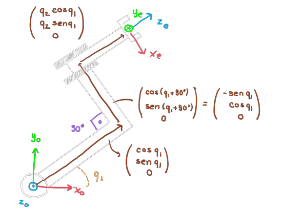
Let's start with the position, \(s(q)\). For this, we sum the following three vectors, all written in the reference frame \(\mathcal{F}_0\):

Forward Kinematics
Exercise 1 - Answer
We have then:
$$s(q) = \LARGE{\Bigg(}\normalsize{}\begin{array}{c} (1+q_2)\cos(q_1)-\sin(q_1) \\ (1+q_2)\sin(q_1)+\cos(q_1) \\ 0 \end{array}\LARGE{\Bigg)}\normalsize{}.$$For the rotation part, we observe that starting from the reference frame \(\mathcal{F}_0\), we make a rotation around the \(z_0\) axis by \(q_1\), then a constant transformation in the current reference frame (\(R_z(-90^o)R_x(-90^o)\)) to align with the end-effector reference frame. We then have the rotation matrix \(Q(q)\):
$$Q(q) = \LARGE{\Bigg(}\normalsize{}\begin{array}{ccc} \sin(q_1) & 0 & \cos(q_1) \\ -\cos(q_1) & 0 & \sin(q_1) \\ 0 & -1 & 0 \\ \end{array}\LARGE{\Bigg)}\normalsize{}.$$Forward Kinematics
Exercise 2 - Answer
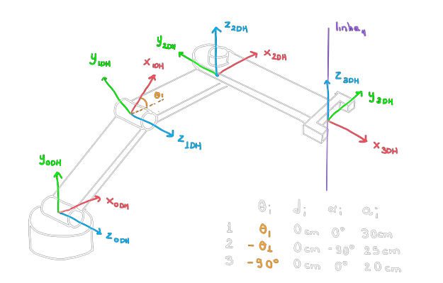
References and parameters. Note that we chose the last row in a convenient way, but neither the first DH reference frame, \(\mathcal{F}_{DH0}\), is the reference frame \(\mathcal{F}_0\), nor the last reference frame, \(\mathcal{F}_{DH3}\), is the end-effector reference frame...

Forward Kinematics
Exercise 2 - Answer
The constant transformations between the initial and final reference frames are:
$$H_{0}^{DH0} = R_z(90^o)R_x(90^o)D_y(10cm) \ , \ H_{DH3}^{e} = R_z(90^o)R_x(90^o).$$Let's calculate the matrices \(H_{0}^{DHi}(q)\) for \(i=1,2,3\) and \(H_0^{e}(q)\):
$$H_{0}^{DH1}(q) = H_0^{DH0}R_z(q_1)D_z(0)R_x(0)D_x(30cm). $$ $$H_{0}^{DH2}(q) = H_{0}^{DH1}(q)R_z(q_2)D_z(0)R_x(-90^o)D_x(25cm). $$ $$H_{0}^{DH3}(q) = H_{0}^{DH2}(q)R_z(q_3)D_z(0)R_x(0)D_x(20cm). $$ $$H_{0}^{e}(q) = H_{0}^{DH3}(q)H_{DH3}^{e}. $$Forward Kinematics
Exercise 2 - Answer
Doing the math, we have:
$$H_{0}^{DH1}(q) = \LARGE{\Bigg(}\small{}\begin{array}{cccc} 0 & 0 & 1 & 0 \\ c_1 & -s_1 & 0 & 0{,}3c_1 \\ s_1 & c_1 & 0 & 0{,}3s_1{+}0,1 \\ 0 & 0 & 0 & 1 \end{array}\LARGE{\Bigg)}\small{} \ , \ H_{0}^{DH2}(q) = \LARGE{\Bigg(}\small{}\begin{array}{cccc} 0 & -1 & 0 & 0 \\ c_{12} & 0 & -s_{12} & 0{,}3c_1{+}0{,}25c_{12}\\ s_{12} & 0 & c_{12} & 0{,}3s_1{+}0{,}25s_{12}{+}0,1\\ 0 & 0 & 0 & 1 \end{array}\LARGE{\Bigg)}\small{}.$$ $$H_{0}^{DH3}(q) = \LARGE{\Bigg(}\small{}\begin{array}{cccc} -s_3 & -c_3 & 0 & -0{,}2s_3 \\ \ c_{12}c_3 & -c_{12}s_3 & -s_{12} & (0{,}2c_3+0{,}25)c_{12} {+} 0{,}3c_1 \\ \ s_{12}c_3 & -s_{12}s_3 & \ c_{12} & (0{,}2c_3+0{,}25)s_{12} {+} 0{,}3s_1{+}0,1 \\ 0 & 0 & 0 & 1 \end{array}\LARGE{\Bigg)}\small{}.$$Forward Kinematics
Exercise 2 - Answer
And therefore, finally:
$$H_{0}^{e}(q) = \LARGE{\Bigg(}\normalsize{}\begin{array}{cccc} -c_3 & 0 & -s_3 & -0{,}2s_3 \\ -c_{12}s_3 & -s_{12} & \ c_{12}c_3 & (0{,}2c_3+0{,}25)c_{12} {+} 0{,}3c_1 \\ -s_{12}s_3 & \ c_{12} & \ s_{12}c_3 & (0{,}2c_3+0{,}25)s_{12} {+} 0{,}3s_1{+}0,1 \\ 0 & 0 & 0 & 1 \end{array}\LARGE{\Bigg)}\normalsize{}.$$Forward Kinematics
Exercise 3 - Answer
Forward Kinematics
Exercise 4 - Answer
Forward Kinematics
Exercise 5 - Answer
Because the rigid rules of Denavit-Hartenberg construction "tie" how one reference frame will be related to the next. Thus, they cannot be generically placed relative to each other, requiring fewer than the 6 minimum parameters needed for generic transformations.

Forward Kinematics
Exercise 6 - Answer
Forward Kinematics
Exercise 7 - Answer
Here is the code:
import uaibot as ub
import numpy as np

# Create the scenario
robot = ub.Robot.create_abb_crb(ub.Utils.trn([0,0,0.2]))

texture_table = ub.Texture(
    url='https://raw.githubusercontent.com/viniciusmgn/uaibot_content/master/contents/Textures/rough_metal.jpg',
    wrap_s='RepeatWrapping', wrap_t='RepeatWrapping', repeat=[1, 1])

material_table = ub.MeshMaterial(texture_map=texture_table, roughness=1, metalness=1, opacity=1)
table1 = ub.Box(name="table1", htm = ub.Utils.trn([0.8,0,0.15]), width=0.5, depth=0.5, height=0.4, mesh_material=material_table)
table2 = ub.Box(name="table2", htm = ub.Utils.trn([0,-0.8,0.15]), width=0.5, depth=0.5, height=0.4, mesh_material=material_table)
table3 = ub.Box(name="table3", htm = ub.Utils.trn([0,0,0.1]), width=0.3, depth=0.3, height=0.2, mesh_material=material_table)
obstacle = ub.Box(name="obstacle", htm = ub.Utils.trn([0.8,-0.8,0.5]), width=0.6, depth=0.6, height=1, mesh_material=material_table)

material_cube = ub.MeshMaterial(roughness=1, metalness=1, opacity=1, color="purple")
cube = ub.Box(name="cube", htm = ub.Utils.trn([0.8,0,0.4]), width=0.1, depth=0.1, height=0.1, mesh_material=material_cube)

sim = ub.Simulation.create_sim_factory([robot, table1, table2, table3, obstacle, cube])

#Resolve o problema

#Encontra a primeira pose alvo
target = table1.htm @ ub.Utils.trn([0,0,0.3]) @ ub.Utils.rotx(np.pi)

#Encontra, por cinemática inversa, uma configuração próxima da atual
#para pegar o bloco por cima
q_target = robot.ikm(htm_target = target, q0 = robot.q)

#Faz o movimento linear no espaço de juntas até pegar o bloco
dt = 0.01
tmax=5
t=0
for i in range(round(tmax/dt)):
  t += dt
  q_c = (1-t/tmax)*robot.q0 + (t/tmax)*q_target
  robot.add_ani_frame(t,q=q_c)

#Pega o bloco no efetuador
robot.attach_object(cube)

#Escolhe uma pose alvo para escapar do obstáculo
target = ub.Utils.trn([0,0,1]) @ ub.Utils.rotx(np.pi/2)

#Encontra, por cinemática inversa, uma configuração próxima da atual
#para chegar lá
q_target = robot.ikm(htm_target = target, q0 = robot.q)


#Faz o movimento linear no espaço de juntas até chegar no alvo atual
dt = 0.01
tmax=5
q0_new = robot.q
t_new = t
for i in range(round(tmax/dt)):
  t += dt
  q_c = (1-(t-t_new)/tmax)*q0_new + ((t-t_new)/tmax)*q_target
  robot.add_ani_frame(t,q=q_c)

#Encontra, por cinemática inversa, uma configuração próxima da atual
#para entregar o bloco
target = table2.htm @ ub.Utils.trn([0,0,0.3]) @ ub.Utils.rotx(np.pi)

#Encontra, por cinemática inversa, uma configuração próxima da atual
#para entregar o bloco, também por cima
q_target = robot.ikm(htm_target = target, q0 = robot.q)

#Faz o movimento linear no espaço de juntas até entregar o bloco
dt = 0.01
tmax=5
q0_new = robot.q
t_new = t
for i in range(round(tmax/dt)):
  t += dt
  q_c = (1-(t-t_new)/tmax)*q0_new + ((t-t_new)/tmax)*q_target
  robot.add_ani_frame(t,q=q_c)

sim.run()